Saturday, October 31, 2009
Submission of draft and Log book
The draft and log book for Final Year Project was submitted on week 13 (23/10/2009). The draft consist of Chapter I & II. Chapter I is Introduction and chapter II is Literature Review. Percentage mark for draft is 5% and log book is 10%.
Thursday, October 22, 2009
Test Method on Add-on SKXBEE
1. Configure the ATMY 1111 to SKXBEE for the robot and ATDL 1111 to SKXBEE for computer using X-TCU (refer User’s manual for SKXBEE section 6.2 for more detail on configuration).
2. Plug in the SKXBEE to the robot and switch ON the power, select “SKXBEE.”
3. Connect another SKXBEE on computer.
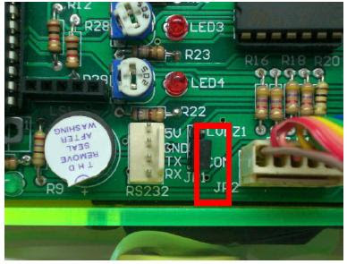
4. Make sure JP1 jumper is connected to COM for UART as shown in Figure.
5. Open X-TCU and click on the terminal, type “d”.
6. Now, user may control the robot using Num pad. 8 to move forward, 4 to turn left, 6 to turn right, and 2 to move backward.
2. Plug in the SKXBEE to the robot and switch ON the power, select “SKXBEE.”
3. Connect another SKXBEE on computer.
4. Make sure JP1 jumper is connected to COM for UART as shown in Figure.
5. Open X-TCU and click on the terminal, type “d”.
6. Now, user may control the robot using Num pad. 8 to move forward, 4 to turn left, 6 to turn right, and 2 to move backward.

Interface XBee Module with PIC Microcontroller
5V and ground is connected to provide power to the module. While TX and RX pin is connected for communication. JP1 jumper is connected at COM for interfacing SKXBEE.

Below is the system overview on how XBee communicate with microcontroller. The XBee will connected to the microcontroller via Universal Asynchronous Receiver/transmitter (UART) pins.

SKXBEE can be add on in the microcontroller circuit. It will lifted a bit high from microcontroller circuit or in other words above the microcontroller circuit. All we need to used is a female header.


Thursday, October 15, 2009
100+ node ZigBee PRO network
Demonstrates how a network of ZigBee PRO nodes based on embedded AVR microcontrollers and Atmel RF transceivers and running BitCloud stack assembles itself in a dense network setting. Provides visual overview of test network environment and WSN Monitor tool for network visualization and control.
This is an example of advanced programming for ZigBEE network..
This is an example of advanced programming for ZigBEE network..
Zigbee / XBee Adapter Configuration Tutorial
This tutorial shows how two XBee Modules can be configured to be able to talk to each other. These modules are ideal for any hobby/school/university project. With these modules it is very easy to interface PC to Microcontroller board, or Microcontroller to Microcontroller over wireless link.
Thursday, October 8, 2009
Mobile Robot Exploration with ZigBee
In this experiment, a mobile robot (red) is equipped with a ZigBee node; another ZigBee node (blue) is emitting a beacon. Using an heuristic algorithm based on LQI (Link Quality Indicator) the robot is able to find the beacon node without entirely explore the search space. This technique can be used, for example, in Search & Rescue scenarios.
Watch video..
Watch video..
Internet Remote Control ZigBee Robot
The Robot is being controlled from Sweden and it's performing a home inspection in real time in a Phoenix home. This is actual video that was recoded in Sweden from the high quality robot WEB based camera..
Watch video..
Watch video..
Draft Chapter 1 & 2 Final Project Thesis
Preparing to do the chapter 1 and 2 final project thesis..The draft need to be submited at week 13at 19/10/2009..
Thursday, October 1, 2009
Approximate Project Cost

Table above shown the approximate cost for the hardware's. The cost will change from time to time depending on the requirement. The cost can be reduced by removing some expensive applications.
How to Build Your First Robot
Robotics can teach you so much.I will learn skills ranging from electronics, mechanics, controls, programming, and even as broad as understanding animal behavior and human psychology. What does an easy to make robot look like? Browse the web for robot galleries. Remember, only bother looking at the really simple robots, DO NOT get imaginative or creative on your first robot. So your first robot will have 2 wheels. It will drive under the most basic algorithm for a robot - differential drive.

Let's start with the wheels. Big wheels will let your robot move faster. Small wheels for slower. So why not just get big? Bigger wheels means your robot has less torque to carry a heavy payload, and bigger wheels generally mean fine position control is harder too. Also, your sensors often cannot keep up with fast changes in position.
Ok now the motors. For an optimal robot choosing motors would involve calculations of weight, gearing ratios, desired terrain, desired velocity and acceleration, voltage, power consumption, controllability and a whole range of things too overwhelming for a beginner. So just wing it. Just make sure you keep your robot as light as possible, and get motors that can do overkill. But remember, bigger the motors, shorter your battery life, and more expensive and complicated your motor control circuitry will get.
Next comes power. No, solar power and eating slugs wont work. Use a battery. When buying a battery make sure they are rechargeable, have high mAh (energy capacity), and can output at least an amp at any time. Consider putting batteries in both parallel and in series to vary/control total voltage and mAh.

Ok now you need a cool circuit thingy. Forget about designing your own. It is best your first robot be simple, so a ready made circuit thingy is easiest. They are usually called microcontrollers, the most popular being PIC, Atmel/AVR, ARM, and BASIC Stamp based. Stamps are easier but offer less functionality.You can also handmake the programmer really cheap. Just make sure the controller you buy has a built in motor driver, LED's, and many analog input/output ports.
Now it is time to DESIGN, THEN BUILD, a robot chassis. A beginner may have difficulty designing just because he/she wouldn't know what does/doesn't work. 3D CAD program that shows placement of all parts, screws, everything. Parts were intentionally designed to require the least amount of drilling and cutting effort. You can never over design, especially when you are in a competition like battlebots where things break often, or don't have enough money/time to waste on mistakes.
This article can be a good guide to a beginner to start do a basic function of robot.Its explained from the simplest technology to the complicated technology.
By Society of robot website
Wednesday, September 16, 2009
Details of X-CTU
The MaxStream X-CTU software, which is also a free download from the MaxStream site, allowed you to use your personal computer to program the XBee modules serially using the XBee DIN,DOUT,RTS, and DTR pins.
X-CTU even provides a built in RS 232 terminal emulator. As we can see in capture below, key register values can be changed within the X-CTU windows and written to the XBee modules mounted on the XBee interface boards. The COM10 XBee module as the coordinator and the COM X XBee module as an end device by setting the XBee modules CE (Coordinator Enable) register to a 1 and 0 (zero) respectively.Assigned a PAN ID of 0xCAFE in the coordinator X-CTU window. The XBee can run in one of three MAC modes:
1) 802.15.4 + Maxstream Header
2) 802.15.4 without ACKs
3) 802.15.4 with ACKs

Monday, September 14, 2009
Wireless Personal Area Network (WPAN)
A personal area network (PAN) is a computer network used for communication among computer devices close to one's person. The devices may or may not belong to the person in question. The reach of a PAN is typically a few meters. PANs can be used for communication among the personal devices themselves , or for connecting to a higher level network and the Internet.
Personal area networks may be wired with computer buses such as USB and FireWire. A wireless personal area network (WPAN) can also be made possible with network technologies such as IrDA, Bluetooth, UWB, Z-Wave and ZigBee.
A WPAN (wireless personal area network) is a personal area network - a network for interconnecting devices centered around an individual person's workspace - in which the connections are wireless. Typically, a wireless personal area network uses some technology that permits communication within about 10 meters - in other words, a very short range.
A key concept in WPAN technology is known as "plugging in". In the ideal scenario, when any two WPAN-equipped devices come into close proximity (within several meters of each other) or within a few kilometers of a central server, they can communicate as if connected by a cable. Another important feature is the ability of each device to lock out other devices selectively, preventing needless interference or unauthorized access to information.Proposed operating frequencies are around 2.4 GHz in digital modes.
By wikipedia.org
Thursday, September 10, 2009
ZigBee Network Topologies
The way that a message is routed from one network node to another depends on the network topology. A ZigBee network can adopt one of the three topologies: Star, Tree, Mesh. These are illustrated on the right and briefly described below.
Star Topology
A Star network has a central node, which is linked to all other nodes in the network. All messages travel via the central node.
Tree Topology
A Tree network has a top node with a branch/leaf structure below. To reach its destination, a message travels up the tree (as far as necessary) and then down the tree.
Mesh Topology
A Mesh network has a tree-like structure in which some leaves are directly linked. Messages can travel across the tree, when a suitable route is available.

Wednesday, September 9, 2009
Communicate Between Two XBee Devices
Before going further,the first step to understand in XBee operation is trying to communicate it between each other (TX-RX) in bidirectional mode..I need to install the driver at 2 PC's which is USB Serial Converter and USB Serial Port..This is to make the XBee compatible with the PC's..After that the X-CTU software need to be installed.

This software will enable user to send and receive a data at a time.The are several configuration need to be determine first such as the Baud Rate = 9600, data bits=8 and stop bits = 1..After that, we must enter the command mode by typing +++ into the terminal area and after that the Xbee's are ready to be operated..The simple diagram on how the XBee communicate is shown below.

But there is a bit problem on communicate the XBee's..The another XBee modules can't be detected by PC..It said "Unable to communicate with the moderm"..This happened at one side only..In my opinion there is something wrong either the hardware or the driver..
Monday, September 7, 2009
ZigBee Devices (FFD & RFD)
The IEEE 802.15.4 specification identifies two devices which is FFD and RFD. The 802.15.4 Full Function Device (FFD) is literally able to do it all. A FFD network will be powered from an inexhaustible power source, which is called out as an AC-fed mains supply, as it must always be active and listening on the network, among other things.
An RFD (Reduced Function Device) perform on recording temperature data, monitoring switches or controlling external devices. The power source of RFD is easily exhaustible and by that RFD is prone to sleep most of the time.
The ZigBee end device can be either an FFD or RFD depending on the application. A ZigBee router is an FFD that enables the extension of the physical range of a ZigBee network. It is used to allows more nodes to join the network as the radio range of the root ZigBee network is effectively increased. The router also can be functioning as a end devices.
Wednesday, September 2, 2009
IEEE 802.15.4
ZigBee is officially a wireless network protocol that is designed to be used with low-data-rate sensor and control networks. ZigBee can also eliminate the need to string wires all over the place as it can easily reach data rates comparable to and above standard RS-232 and RS-485 wired protocols. Although an IEEE 802.15.4 network can easily obtain RS-232 speeds, you wont see many battery powered applications of IEEE 802.15.4 networks replacing RS-232 communication links,especially if the traffic on the IEEE 802.15.4 based pseudo RS-232 link is heavy.

ZigBee is a standards based network protocol supported solely by the ZigBee Aliance that uses the transport services of the IEEE 802.15.4 network specification. The IEEE 802.15.4 specification also uses internal layers, which are normally referred to as sublayers. The wireless 802.11b specification and the wired 802.3 specification also employ the concept of sublayers. The IEEE 802.15.4 specification calls out a pair of 802.15.4 sublayers, the PHY and the MAC.
If we relate the IEEE 802.15.4 sublayers to the ZigBee protocol stack, the ZigBee PHY sublayer, which is actually the IEEE 802.15.4 PHY sublayer, is all about the radio and the generation of the radio link. A ZigBee stacks PHY responsibilities include receiver energy detection, link quality indication and clear channel assesment. The ZigBee stacks PHY is also primarily responsible for transmitting and receiving packets across the magnetic medium. The ability to sniff the air for other nodes is very important in the ZigBee and IEEE 802.15.4 world as this is what is done to determine if a new ZigBee or IEEE 802.15.4 network can be spawned.
Saturday, August 29, 2009
Robot Rising Program at Astro Discovery Science
This program was shown at Astro Discovery Science (CH 553)..I watched the program for a hour..This program is about the development of robotic technology around the world..Many robots develop based on ideas from movies for example star wars robot and others fictions.They try to rebuild the robot based from animation. For about a hour the documentary shown the Massachusetts Institute of Technology (MIT) department engineers works on different types of robot.There is an unique robot which an aquatic robot.It is called "robo tuna".It has complex mechanical and circuit which is waterproof.
MIT also tried to communicate between a robot using ants communication concept which transfer data to each others. They also under development of nano technology implementation on the robot. By using nano technology the size of robot can be smaller.NASA also develop their own robot technology. They will created robot that will be place on others planet. There is a robot created by NASA which "Rocky 7".Nasa concluded that that robot must be tough at any rough material. Their robots is created in 6 wheels which is it is good for rough surface.
MIT also tried to communicate between a robot using ants communication concept which transfer data to each others. They also under development of nano technology implementation on the robot. By using nano technology the size of robot can be smaller.NASA also develop their own robot technology. They will created robot that will be place on others planet. There is a robot created by NASA which "Rocky 7".Nasa concluded that that robot must be tough at any rough material. Their robots is created in 6 wheels which is it is good for rough surface.
Thursday, August 27, 2009
XBee Maxstream Module Types

Two versions are available from MaxStream: XBee and XBee PRO. Both versions are functionally identical and pin compatible. The only difference is the transmit power, which is 1 mW maximum for the XBee and 63 mW maximum for the XBee PRO. Of course, transmit power is an important factor because the range of the ultimate product depends on it, but it is certainly not the only thing you have to take into account. Another consideration that is at least as important is that higher transmit power means higher current consumption. A transmit power of 1 mW already costs around 45 mA, while 63 mW from the antenna translates into a tidy 270 mA from the power source. A further consideration is compliance with legal requirements. The maximum radiated power is regulated by law, and in Europe the applicable limit is 10 mW. To make it possible to comply with this requirement, MaxStream has implemented a configuration parameter in the XBee that can be used to set the transmit power.

XBee is available with three different types of antenna.
Simplified View of the Actual XBee Hardware

Figure above is a simplified depiction of the XBee module’s internals. Incoming data flowing through the DIN pin is buffered by the DIN buffer until it can be transmitted. As programmer and commander, you have the option of sending characters as they enter the DIN pin or buffering up a number of characters to send as a packet. When the XBee module isn’t sending characters, it can rest in Idle mode, enter Receive mode, process a command, or just sleep it off. The bulk of the subsystem boxes shown in Figure above are contained within two Freescale Semiconductor physical ICs: an MC9S08GT60 microcontroller and an MC13193 802.15.4 RF transceiver IC.
Wednesday, August 26, 2009
XBee ZigBee Module
ZigBee’s mission is to cut the traditional wires between sensors, wired slave devices, and the microcontrollers and microprocessors they serve. Thus, if ZigBee is to emulate a wire, what goes in must come out without any significant change. MaxStream’s XBee ZigBee modules feature a UART interface, which allows any microcontroller or microprocessor to immediately use the services of the ZigBee protocol. All a ZigBee hardware designer has to do in this case is ensure that the host’s serial port logic levels are compatible with the XBee’s 2.8- to 3.4-V logic levels. The logic level conversion can be performed using either a standard RS- 232 IC or logic level translators such as the 74LVTH125 when the host is directly connected to the XBee UART.
By Fredy Edy/Applied PCs
By Fredy Edy/Applied PCs
Tuesday, August 25, 2009
The Making of Final Year Project Proposal
Start to do proposal for Final Year Project..The submission for the proposal is on week 7 by 1/9/2009..Mark percentage for this proposal is 5% over 100%...The content of the proposal are the problem statement, objectives of the project, methodology, resource planning, estimation costing, the flow of the project and so on..
Thursday, August 20, 2009

Wednesday, August 19, 2009
Operation of H-Bridge

The H-Bridge arrangement is generally used to reverse the polarity of the motor, but can also be used to 'brake' the motor, where the motor comes to a sudden stop, as the motor's terminals are shorted, or to let the motor 'free run' to a stop, as the motor is effectively disconnected from the circuit. The following table summarises operation.
Introduction to H-Bridge

An H-bridge is an electronic circuit which enables a voltage to be applied across a load in either direction. These circuits are often used in robotics and other applications to allow DC motors to run forwards and backwards. H-bridges are available as integrated circuits, or can be built from discrete components.
The term "H-bridge" is derived from the typical graphical representation of such a circuit. An H-bridge is built with four switches (solid-state or mechanical). When the switches S1 and S4 are closed (and S2 and S3 are open) a positive voltage will be applied across the motor. By opening S1 and S4 switches and closing S2 and S3 switches, this voltage is reversed, allowing reverse operation of the motor.
The switches S1 and S2 should never be closed at the same time, as this would cause a short circuit on the input voltage source. The same applies to the switches S3 and S4. This condition is known as shoot-through.
I think H bridge is the most suitable concept in this project which is to control the speed of stepper motor.. A simulation of this bridge will be test soon.
Friday, August 14, 2009
Sample of programming for Stepper Motor using C Programming & Assembly
-C Programming-
#include.
#define stepper P1
void delay();
void main(){
while(1){
stepper = 0x0C;
delay();
stepper = 0x06;
delay();
stepper = 0x03;
delay();
stepper = 0x09;
delay();
}
}
void delay(){
unsigned char i,j,k;
for(i=0;i<6;i++)
for(j=0;j<255;j++)
for(k=0;k<255;k++);
-Assembly Language-
ORG 0H
stepper equ P1
main:
mov stepper, #0CH
acall delay
mov stepper, #06H
acall delay
mov stepper, #03H
acall delay
mov stepper, #09H
acall delay
sjmp main
delay:
mov r7,#4
wait2:
mov r6,#0FFH
wait1:
mov r5,#0FFH
wait:
djnz r5,wait
djnz r6,wait1
djnz r7,wait2
ret
end
#include
#define stepper P1
void delay();
void main(){
while(1){
stepper = 0x0C;
delay();
stepper = 0x06;
delay();
stepper = 0x03;
delay();
stepper = 0x09;
delay();
}
}
void delay(){
unsigned char i,j,k;
for(i=0;i<6;i++)
for(j=0;j<255;j++)
for(k=0;k<255;k++);
-Assembly Language-
ORG 0H
stepper equ P1
main:
mov stepper, #0CH
acall delay
mov stepper, #06H
acall delay
mov stepper, #03H
acall delay
mov stepper, #09H
acall delay
sjmp main
delay:
mov r7,#4
wait2:
mov r6,#0FFH
wait1:
mov r5,#0FFH
wait:
djnz r5,wait
djnz r6,wait1
djnz r7,wait2
ret
end
Wednesday, August 12, 2009
Operation of server motor
When we energize a coil of stepper motor, The shaft of stepper motor (which is actually a permanent magnet) align itself according to poles of energized coil. So when motor coils are energized in a particular sequence, motor shaft tend to align itself according to pole of coils and hence rotates. A small example of energizing operation is given below.


Stepper Motor

Stepper motor can be used in various areas in microcontroller projects such as making robots, robotic arm, door lock system and so on. So, stepper motor is suitable to be used in this project and must be considered with others motors. There are 2 types of stepper motors which is bipolar and unipolar.
Unipolar stepper motor
The unipolar stepper motor has five or six wires and four coils. The center connections of the coils are tied together and used as the power connection. They are called unipolar steppers because power always comes in on this one pole.
Bipolar stepper motor
The bipolar stepper motor usually has four wires coming out of it. Unlike unipolar steppers, bipolar steppers have no common center connection. They have two independent sets of coils instead. It can be distinguish from unipolar steppers by measuring the resistance between the wires.
Monday, August 10, 2009
PIC 16F877A Pin Out
Ports A and E become ANALOGUE INPUTS by default (on power up or reset), so they have to set up for digital I/O if required. Port B is used for downloading the program to the chip flash ROM (RB6 and RB7), and RB0 and RB4–RB7 can generate an interrupt. Port C gives access to timers and serial ports, while Port D can be used as a slave port, with Port E providing the control pins for this function.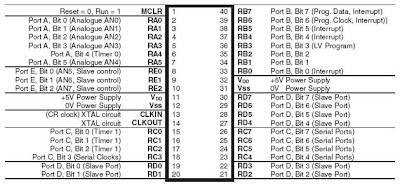

Sunday, August 9, 2009
PIC16F877A Training 7/8/2009
Pic training was held in laboratory level 4 and conducted by Sir Zulkhairi itself..The purpose of this training is to teach the student on the basic of PIC hardware and software..The 1st programming is how t o operate an LED on the output port..This PIC has 40 pins and has 5 input/output port,15 interrupt and also have Parallel Slave Port. Operating frequency for this PIC is 20 MHz. Here are some of the specification for PIC16F877A --Flash memory is 8K, EEPROM 256, data memory is368 and timers are 3. Software used to simulate the circuit is Proteus and PCW is to compile the program..
 o operate an LED on the output port..This PIC has 40 pins and has 5 input/output port,15 interrupt and also have Parallel Slave Port. Operating frequency for this PIC is 20 MHz. Here are some of the specification for PIC16F877A --Flash memory is 8K, EEPROM 256, data memory is368 and timers are 3. Software used to simulate the circuit is Proteus and PCW is to compile the program..
Wednesday, August 5, 2009
Example of some famous autonomous robot.


This is some example of autonomous robot that will be used for Zigbee applications. It will use two wheels or maybe more, depending on the requirement.
Project Brief
In this project, student will built a navigation control subsytem for an autonomous differential steering explorer robot. Specially, it is a robotic platform that drives motors and controls an H-bridge and also presents a wireless communication system that remotely manages the robot.
Origin of ZigBee???
Articles published by technology news organizations such as EDN and Telecommunications Online claim that the term "ZigBee" originates from the zig-zag waggle dance honeybees use to share critical information, such as the location, distance, and direction of a newly discovered food source, with fellow hive members. ZigBee device manufacturer Meshnetics refers to this communication system as the "ZigBee Principle". However, no such term exists in apiology, the scientific study of honeybees. Robert Metcalfe, inventor of Ethernet and a contributor on the initial development of Zigbee, confirmed to a journalist in 2004 that the name was initially meaningless and had been chosen from a long list on the basis that it had no trademark liabilities.
By wikipedia.org
By wikipedia.org
ZigBee History
- ZigBee-style networks began to be conceived about 1998, when many installers realized that both WiFi and Bluetooth were going to be unsuitable for many applications. In particular, many engineers saw a need for self-organizing ad-hoc digital radio networks.
- The IEEE 802.15.4 standard was completed in May 2003.
- In the summer of 2003, Philips Semiconductors, a major mesh network supporter, ceased the investment. Philips Lighting has, however, continued Philips' participation, and Philips remains a promoter member on the ZigBee Alliance Board of Directors.
- The ZigBee Alliance announced in October 2004 that the membership had more than doubled in the preceding year and had grown to more than 100 member companies, in 22 countries. By April 2005 membership had grown to more than 150 companies, and by December 2005 membership had passed 200 companies.
- The ZigBee specifications were ratified on 14 December 2004.
- The ZigBee Alliance announces public availability of Specification 1.0 on 13 June 2005, known as ZigBee 2004 Specification.
- The ZigBee Alliance announces the completion and immediate member availability of the enhanced version of the ZigBee Standard in September 2006, known as ZigBee 2006 Specification.
- During the last quarter of 2007, ZigBee PRO, the enhanced ZigBee specification was finalized.
Saturday, July 25, 2009
My 1st project blog..
This is the only one blog for my final project during my degree at UniKL-BMI..Hope its going to be interesting soon..
Wednesday, July 22, 2009
The topic and supervisor and Final Year Project Briefing
The topic is Zigbee Application : Autonomous robot..The supervisor is Sir Zulkhairi Mohd. Yusof.. The briefing was handled by Prof. Dr. Badri and he is the coordinator for final year project..The briefing was done in 2 hours and the content is to tell the student the procedure and flow how to do final year project..The logbook is for the first time introduce to final year project student..Student must update the logbook until at the end of the project.
Subscribe to:
Comments (Atom)

