This program was shown at Astro Discovery Science (CH 553)..I watched the program for a hour..This program is about the development of robotic technology around the world..Many robots develop based on ideas from movies for example star wars robot and others fictions.They try to rebuild the robot based from animation. For about a hour the documentary shown the Massachusetts Institute of Technology (MIT) department engineers works on different types of robot.There is an unique robot which an aquatic robot.It is called "robo tuna".It has complex mechanical and circuit which is waterproof.
MIT also tried to communicate between a robot using ants communication concept which transfer data to each others. They also under development of nano technology implementation on the robot. By using nano technology the size of robot can be smaller.NASA also develop their own robot technology. They will created robot that will be place on others planet. There is a robot created by NASA which "Rocky 7".Nasa concluded that that robot must be tough at any rough material. Their robots is created in 6 wheels which is it is good for rough surface.
Saturday, August 29, 2009
Thursday, August 27, 2009
XBee Maxstream Module Types

Two versions are available from MaxStream: XBee and XBee PRO. Both versions are functionally identical and pin compatible. The only difference is the transmit power, which is 1 mW maximum for the XBee and 63 mW maximum for the XBee PRO. Of course, transmit power is an important factor because the range of the ultimate product depends on it, but it is certainly not the only thing you have to take into account. Another consideration that is at least as important is that higher transmit power means higher current consumption. A transmit power of 1 mW already costs around 45 mA, while 63 mW from the antenna translates into a tidy 270 mA from the power source. A further consideration is compliance with legal requirements. The maximum radiated power is regulated by law, and in Europe the applicable limit is 10 mW. To make it possible to comply with this requirement, MaxStream has implemented a configuration parameter in the XBee that can be used to set the transmit power.

XBee is available with three different types of antenna.
Simplified View of the Actual XBee Hardware

Figure above is a simplified depiction of the XBee module’s internals. Incoming data flowing through the DIN pin is buffered by the DIN buffer until it can be transmitted. As programmer and commander, you have the option of sending characters as they enter the DIN pin or buffering up a number of characters to send as a packet. When the XBee module isn’t sending characters, it can rest in Idle mode, enter Receive mode, process a command, or just sleep it off. The bulk of the subsystem boxes shown in Figure above are contained within two Freescale Semiconductor physical ICs: an MC9S08GT60 microcontroller and an MC13193 802.15.4 RF transceiver IC.
Wednesday, August 26, 2009
XBee ZigBee Module
ZigBee’s mission is to cut the traditional wires between sensors, wired slave devices, and the microcontrollers and microprocessors they serve. Thus, if ZigBee is to emulate a wire, what goes in must come out without any significant change. MaxStream’s XBee ZigBee modules feature a UART interface, which allows any microcontroller or microprocessor to immediately use the services of the ZigBee protocol. All a ZigBee hardware designer has to do in this case is ensure that the host’s serial port logic levels are compatible with the XBee’s 2.8- to 3.4-V logic levels. The logic level conversion can be performed using either a standard RS- 232 IC or logic level translators such as the 74LVTH125 when the host is directly connected to the XBee UART.
By Fredy Edy/Applied PCs
By Fredy Edy/Applied PCs
Tuesday, August 25, 2009
The Making of Final Year Project Proposal
Start to do proposal for Final Year Project..The submission for the proposal is on week 7 by 1/9/2009..Mark percentage for this proposal is 5% over 100%...The content of the proposal are the problem statement, objectives of the project, methodology, resource planning, estimation costing, the flow of the project and so on..
Thursday, August 20, 2009

Wednesday, August 19, 2009
Operation of H-Bridge

The H-Bridge arrangement is generally used to reverse the polarity of the motor, but can also be used to 'brake' the motor, where the motor comes to a sudden stop, as the motor's terminals are shorted, or to let the motor 'free run' to a stop, as the motor is effectively disconnected from the circuit. The following table summarises operation.
Introduction to H-Bridge

An H-bridge is an electronic circuit which enables a voltage to be applied across a load in either direction. These circuits are often used in robotics and other applications to allow DC motors to run forwards and backwards. H-bridges are available as integrated circuits, or can be built from discrete components.
The term "H-bridge" is derived from the typical graphical representation of such a circuit. An H-bridge is built with four switches (solid-state or mechanical). When the switches S1 and S4 are closed (and S2 and S3 are open) a positive voltage will be applied across the motor. By opening S1 and S4 switches and closing S2 and S3 switches, this voltage is reversed, allowing reverse operation of the motor.
The switches S1 and S2 should never be closed at the same time, as this would cause a short circuit on the input voltage source. The same applies to the switches S3 and S4. This condition is known as shoot-through.
I think H bridge is the most suitable concept in this project which is to control the speed of stepper motor.. A simulation of this bridge will be test soon.
Friday, August 14, 2009
Sample of programming for Stepper Motor using C Programming & Assembly
-C Programming-
#include.
#define stepper P1
void delay();
void main(){
while(1){
stepper = 0x0C;
delay();
stepper = 0x06;
delay();
stepper = 0x03;
delay();
stepper = 0x09;
delay();
}
}
void delay(){
unsigned char i,j,k;
for(i=0;i<6;i++)
for(j=0;j<255;j++)
for(k=0;k<255;k++);
-Assembly Language-
ORG 0H
stepper equ P1
main:
mov stepper, #0CH
acall delay
mov stepper, #06H
acall delay
mov stepper, #03H
acall delay
mov stepper, #09H
acall delay
sjmp main
delay:
mov r7,#4
wait2:
mov r6,#0FFH
wait1:
mov r5,#0FFH
wait:
djnz r5,wait
djnz r6,wait1
djnz r7,wait2
ret
end
#include
#define stepper P1
void delay();
void main(){
while(1){
stepper = 0x0C;
delay();
stepper = 0x06;
delay();
stepper = 0x03;
delay();
stepper = 0x09;
delay();
}
}
void delay(){
unsigned char i,j,k;
for(i=0;i<6;i++)
for(j=0;j<255;j++)
for(k=0;k<255;k++);
-Assembly Language-
ORG 0H
stepper equ P1
main:
mov stepper, #0CH
acall delay
mov stepper, #06H
acall delay
mov stepper, #03H
acall delay
mov stepper, #09H
acall delay
sjmp main
delay:
mov r7,#4
wait2:
mov r6,#0FFH
wait1:
mov r5,#0FFH
wait:
djnz r5,wait
djnz r6,wait1
djnz r7,wait2
ret
end
Wednesday, August 12, 2009
Operation of server motor
When we energize a coil of stepper motor, The shaft of stepper motor (which is actually a permanent magnet) align itself according to poles of energized coil. So when motor coils are energized in a particular sequence, motor shaft tend to align itself according to pole of coils and hence rotates. A small example of energizing operation is given below.


Stepper Motor

Stepper motor can be used in various areas in microcontroller projects such as making robots, robotic arm, door lock system and so on. So, stepper motor is suitable to be used in this project and must be considered with others motors. There are 2 types of stepper motors which is bipolar and unipolar.
Unipolar stepper motor
The unipolar stepper motor has five or six wires and four coils. The center connections of the coils are tied together and used as the power connection. They are called unipolar steppers because power always comes in on this one pole.
Bipolar stepper motor
The bipolar stepper motor usually has four wires coming out of it. Unlike unipolar steppers, bipolar steppers have no common center connection. They have two independent sets of coils instead. It can be distinguish from unipolar steppers by measuring the resistance between the wires.
Monday, August 10, 2009
PIC 16F877A Pin Out
Ports A and E become ANALOGUE INPUTS by default (on power up or reset), so they have to set up for digital I/O if required. Port B is used for downloading the program to the chip flash ROM (RB6 and RB7), and RB0 and RB4–RB7 can generate an interrupt. Port C gives access to timers and serial ports, while Port D can be used as a slave port, with Port E providing the control pins for this function.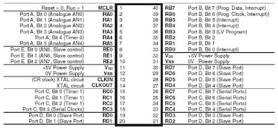

Sunday, August 9, 2009
PIC16F877A Training 7/8/2009
Pic training was held in laboratory level 4 and conducted by Sir Zulkhairi itself..The purpose of this training is to teach the student on the basic of PIC hardware and software..The 1st programming is how t o operate an LED on the output port..This PIC has 40 pins and has 5 input/output port,15 interrupt and also have Parallel Slave Port. Operating frequency for this PIC is 20 MHz. Here are some of the specification for PIC16F877A --Flash memory is 8K, EEPROM 256, data memory is368 and timers are 3. Software used to simulate the circuit is Proteus and PCW is to compile the program..
 o operate an LED on the output port..This PIC has 40 pins and has 5 input/output port,15 interrupt and also have Parallel Slave Port. Operating frequency for this PIC is 20 MHz. Here are some of the specification for PIC16F877A --Flash memory is 8K, EEPROM 256, data memory is368 and timers are 3. Software used to simulate the circuit is Proteus and PCW is to compile the program..
Wednesday, August 5, 2009
Example of some famous autonomous robot.


This is some example of autonomous robot that will be used for Zigbee applications. It will use two wheels or maybe more, depending on the requirement.
Project Brief
In this project, student will built a navigation control subsytem for an autonomous differential steering explorer robot. Specially, it is a robotic platform that drives motors and controls an H-bridge and also presents a wireless communication system that remotely manages the robot.
Origin of ZigBee???
Articles published by technology news organizations such as EDN and Telecommunications Online claim that the term "ZigBee" originates from the zig-zag waggle dance honeybees use to share critical information, such as the location, distance, and direction of a newly discovered food source, with fellow hive members. ZigBee device manufacturer Meshnetics refers to this communication system as the "ZigBee Principle". However, no such term exists in apiology, the scientific study of honeybees. Robert Metcalfe, inventor of Ethernet and a contributor on the initial development of Zigbee, confirmed to a journalist in 2004 that the name was initially meaningless and had been chosen from a long list on the basis that it had no trademark liabilities.
By wikipedia.org
By wikipedia.org
ZigBee History
- ZigBee-style networks began to be conceived about 1998, when many installers realized that both WiFi and Bluetooth were going to be unsuitable for many applications. In particular, many engineers saw a need for self-organizing ad-hoc digital radio networks.
- The IEEE 802.15.4 standard was completed in May 2003.
- In the summer of 2003, Philips Semiconductors, a major mesh network supporter, ceased the investment. Philips Lighting has, however, continued Philips' participation, and Philips remains a promoter member on the ZigBee Alliance Board of Directors.
- The ZigBee Alliance announced in October 2004 that the membership had more than doubled in the preceding year and had grown to more than 100 member companies, in 22 countries. By April 2005 membership had grown to more than 150 companies, and by December 2005 membership had passed 200 companies.
- The ZigBee specifications were ratified on 14 December 2004.
- The ZigBee Alliance announces public availability of Specification 1.0 on 13 June 2005, known as ZigBee 2004 Specification.
- The ZigBee Alliance announces the completion and immediate member availability of the enhanced version of the ZigBee Standard in September 2006, known as ZigBee 2006 Specification.
- During the last quarter of 2007, ZigBee PRO, the enhanced ZigBee specification was finalized.
Subscribe to:
Posts (Atom)

